|
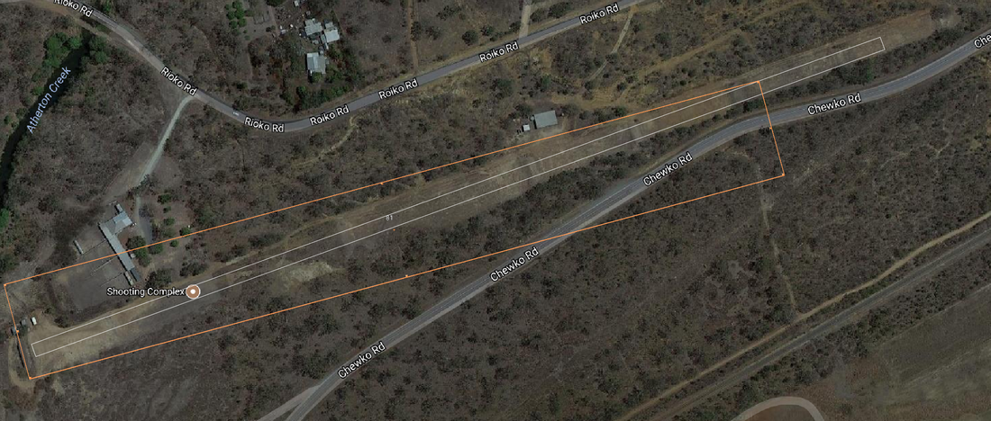
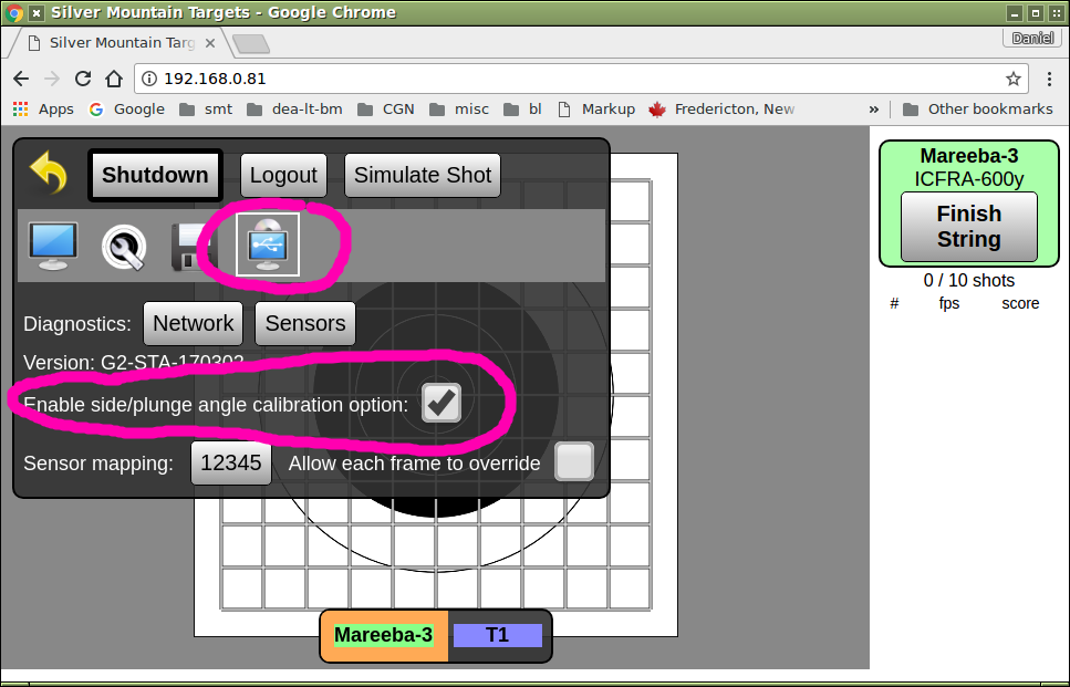
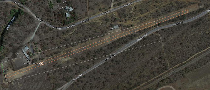
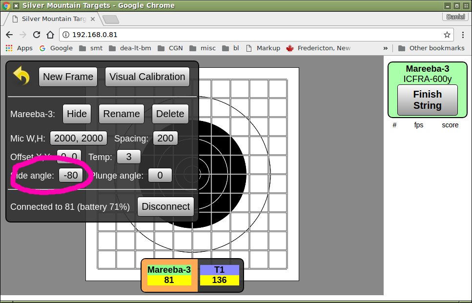
Sometimes Rule 1 TRY FOR PERFECTION in your setup is not possible or convenient. One of the great things about outdoor target rifle shooting is getting to shoot at different ranges. One of the true pleasures of running an electronic targets company is getting to visit more ranges than I otherwise might, and to work with people all over the world on many different and interesting rifle ranges. Here is a nice range in Mareeba, in northern Queensland, Australia. Open it up in googlemaps and try one of my favourite hobbies, which exploring rifle ranges from afar. Zoom in on the targets area and you might be able to see that the target line at Mareeba has been built at a bit of an angle with respect to the main range axis and therefore the incoming bullet path. While most military ranges are built like parade squares, precisely surveyed and with every angle a perfect right angle, it is surprisingly common for civilian-built ranges to have their firing line built not exactly perpendicular to the incoming bullet path. Fortunately, this "fault" basically doesn't matter and in no way affects the usefulness or fairness of the range. I took a screenshot from googlemaps and then used a graphics editing program to create an orange rectangle that is aligned with the row of targets, and a white rectangle that is aligned with the shooting axis of the range. You can see the extent to which Mareeba's target line is not perpendicular to the incoming bullets. The target face on this range doesn't actually point directly at the shooter., it actually points a good deal to one side of the shooter. A carefully-installed set of microphones on a target face here would end up not actually pointing at the shooter, which is what the internal calculation math assumes. If we don't do something about this, a careful shooter might be able to notice some measurement errors (mostly in the sideways component of the reported bullet position). So - if we want to install an e-target here and have it give us the utmost precision, what should we do? One way would be to mechanically alter the mounting arrangements for each target frame, so that the target face DOES point to the shooters. Sometimes this is an easy and practical solution, if so that's the route you should take - alter the mounting arrangements of the targetframe so as to directly counteract the angle of the range itself. Another way, which is the subject of this article, is to have the SMT software correct for this during the calculation process. Let's get started. First, we must turn on this advanced option. Become ADMIN, click on the GEARWHEEL, then the "USB" sub=menu and tick the "Enable side/plunge angle calibration option:" box: 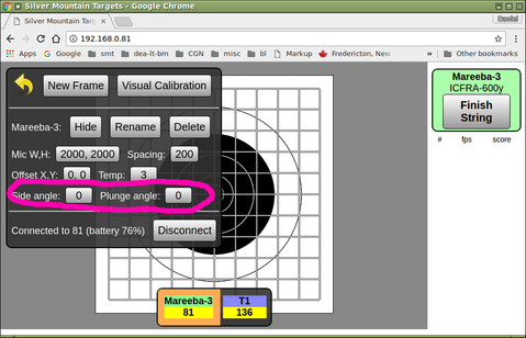 Now when you go to the ADMIN -> TARGETFRAME screen,you will see two new fields available, for us to tell the software the known amount that the targetface is NOT perpendicular in the side-to-side direction or the vertical direction. For now they are zero, meaning that the e-target assumes everything is at perfect right angles The units of side-angle and pluing-angle are mils (milliradians). An angle of one mil is one part in a thousand, which is a pretty convenient way to measure angles for our purposes here. We know from my brief graphics exercise above that the shooter's position on the firing point is a certain amount to the RIGHT the the hypothetical line that the targetface is pointing. If one of your club members or friends is a surveyor, invite him out and he can tell you the angle you need to know. Or, you can make an approximate (and good enough for our purposes) measurement with your graphics program. How you do that will depend on your graphics program - if it is able to measure angles for you, do that and you are done. My graphics program didn't let me directly measure angles but it did let me measure distances. Here is what I have done. Have a look at that first picture again (click here for higher-res), but note that I have added a GREEN bar, which is the amount of sideways displacement (to the nearest metre or two) of how far sideways the 600 yard firing point is displaced: From this exercise I can see that green line is 50 yards long, meaning that a shooter lying down in his designate position on the 600 yard firing line is actually about 50 yards north(ish) of where he "should" be, if he were to be perfectly aligned with the target. To calculate the angle you divide the sideways displacement by the distance to the target, an then multiply by 1000 in order to give the result in units of mil , So in this case it is 50 yards divided by 600 yards times 1000mils which equals 80 mils. Because the shooter is to the RIGHT of where he "should" be, the angle we use has a negative sign. If the shooter were to the left we would use the same number but it would be positive. Here is how we tell the targetframe that we expect all of our bullets to be arriving at an angle of minus 80 mils: Now when you go shoot, you should see the at-target bullet speeds agree with the predictions of your ballistics program. And, sideways "stretching" or "shrinking" should be eliminated.
5 Comments
This article will tell you how to get the very best possible accuracy from your system. In many practical use-cases of your SMT G2-ShootersPac you can skip some of the fussier steps here and still get results "good enough" for your purposes and that is the subject of another article. But if you need or want the highest achievable measurement accuracy, read on.... To get the best possible accuracy requires attention in three areas
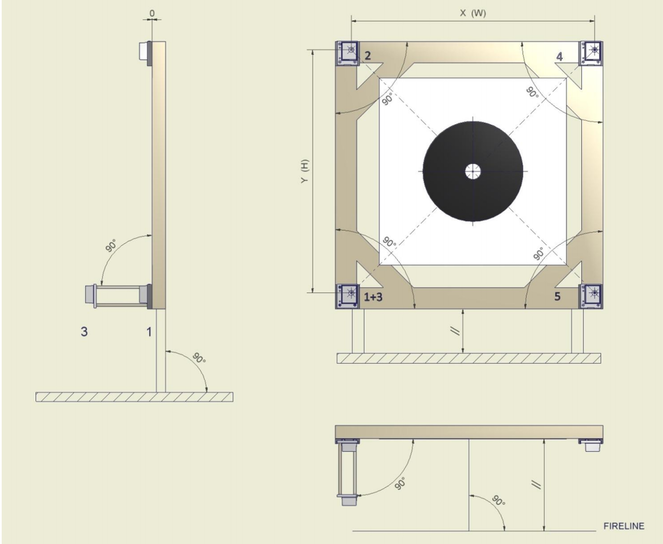
This sketch shows an ideal installation of the sensors on the target, and the ideal direction for shooting (incoming bullets directly perpendicular to the target face and sensor plane): If any of the above are wrong or poorly done your e-target will still work, but every shot it reports will contain a systematic error.
Rule 1 is TRY FOR PERFECTION in your setup; the better your setup the better your measurements will be. Rule 2 is IF YOU CAN'T MAKE IT PERFECT, ASK SMT FOR ADVICE. There are some systematic imperfections that can be compensated-for in software; when in doubt, consult with your SMT dealer and ask for help. Here are detail descriptions of the above points locations of sensors on target frame The mic sensor mounting plates are expected to be in a "rectangular geometry", that is to say the horizontal and vertical spacings between the mics can be different, but they need to be set up in a perpendicular manner. Please measure your horizontal ("WIDTH") and vertical ("HEIGHT") spacing to within 10mm. perpendicularity of chrono mic to target face This is the single most important item to get correct. This can be a very fussy thing to set up correctly but it is well worth your while to get the front mic (#3) within 2mm of being perfectly perpendicular to the target face, in both the horizontal and vertical directions. If necessary, shim or otherwise adjust your mounting plate until the front mic and rear mic are as close to perfectly perpendicular as you are able to achieve. plumbness (verticality) of target face The ideal orientation for the target face is perfectly vertical. If this is not possible, a small but constant tilt angle is the next best thing. The most troublesome setup is on a moveable target carrier mechanism that has a certain amount of "slop", that allows the wind to blow the target face so that it tilts backwards or forwards, and produces a variable (and unknown!) angle of tilt. If possible, shim or wedge the target carrier frame to minimize or eliminate fore-and-aft tilt angle changes. temperature sensor shaded from sunlight A correct temperature reading is required in order to accurately calculate shot position. The temperature sensor element (the fourth lead of the main branch of the wiring harness, which does not have a BNC connector) should be placed in a location in which air is able to flow over it freely, but it must not be exposed to direct sunlight - otherwise the temperature will vary by up to 15C depending on the intensity of the sunlight falling on it. Arrange for the temperature sensor to be shaded for the duration of your shooting. verify all sensors working (tap test) You can do this at home, or you can do this on at the range as you are setting up your gear getting ready to shoot. When you are in the ADMIN -> TARGETFRAME menu, very lightly tapping a microphone sensor element with your fingernail will cause the microphone to fire and a large green number (e.g. "4") to display on your screen for several seconds. This confirms that the mic and all harness wiring are fully functional. verify temperature sensor calibration correct This can be done as part of the "tap test". Examine the temperature that is read when you tap a mic, and confirm that it is within 1-2C of the correct air temperature. calibration shots to correct for any errors in placement Any fixed offset errors of the target face paper relative to the physical centre of the sensor array can easily be measured and completely compensated for by firing a shot near the middle of the target (10-ring/5-ring or better) and entering the measured shot location. After this verify calibration After your system is properly set up, is reading the air temperature correctly, and has been calibrated, you can easily check to see if you are experiencing systematic errors or not.
The shooter should be firing directly at the target in a perpendicular manner. If this is not possible (some ranges are built "crooked"), it is possible to correct for this in software - please consult with SMT for details on how to measure this and how to configure the software accordingly. |
AuthorWrite something about yourself. No need to be fancy, just an overview. ArchivesCategories |
|
for shooters, by shooters
[email protected] |

 RSS Feed
